The basic parts of an air compressor include a motor, pump, storage tank, intake valve/filter, regulator, control panel, check valve, discharge line, outlet, and pressure switch to name a few.
In this article, I will bring you on a journey to unravel the inner workings of an air compressor, By understanding the various parts that make up this machine, we can gain a deeper appreciation for its versatility and utility in different industries and in your home as well.
Now let’s dive deeper into the parts of the three main compressor types.
Table of Contents
- Single-Stage Air Compressor Diagram & Parts
- Two-Stage Air Compressor Diagram & Parts
- Rotary Screw Air Compressor & Dryer Diagram & Parts
- FAQs (Frequently Asked Questions)
Single-Stage Air Compressor Diagram & Parts
A single-stage reciprocating air compressor is a type of compressor that operates on a single level of compression. It is commonly used for small to medium-sized applications that require moderate air pressure. This compressor’s main part is a single piston motor or rotor that compresses the air directly into a storage tank or receiver.
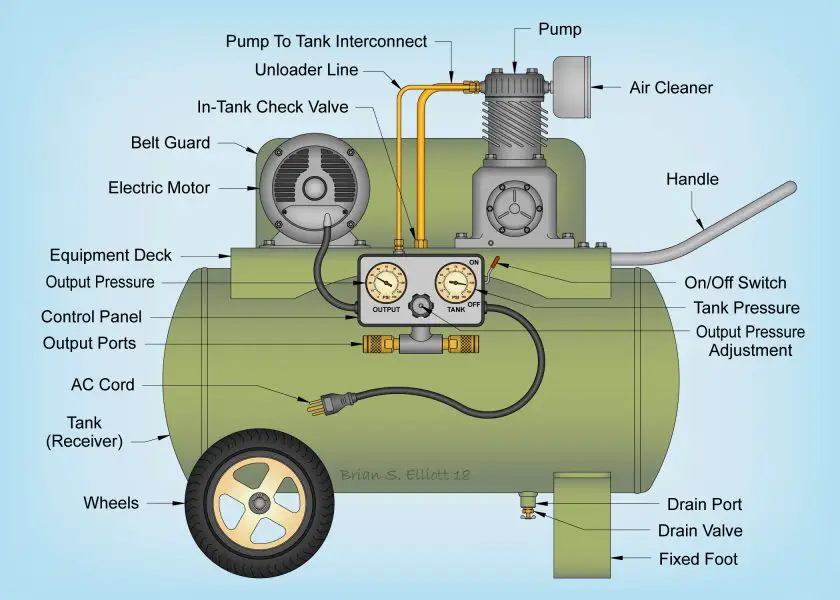
Wheels, Handle & Fixed Foot
The wheels, handle, and fixed foot of the single-stage air compressor are there to allow the portability and stability of the compressor.
Wheels provide mobility, allowing the compressor to be easily transported from one location to another. These sturdy, often rubberized wheels are designed to roll smoothly over various surfaces, making it convenient to move the compressor to different work areas. You can obviously do that with the help of the handle. The handle is located at the top of the compressor. Once you decide where you want to place your compressor you can lower it to the ground and let it rest on the fixed foot.
Combined, these features enable the air compressor to be effortlessly moved and positioned while maintaining stability, making it a versatile and user-friendly tool for various applications.
Tank Receiver
A compressed air receiver tank, or otherwise referred to as an air tank or a compressed air storage tank, is everything it says it is… a tank that receives compressed air and stores it after it exits the air compressor chamber.
The tank receiver is typically a cylindrical or rectangular vessel, usually made of steel. It is designed to withstand the high pressure generated by the compressor and is equipped with safety valves to prevent over-pressurization.
Once the air is compressed by the single-stage compressor, it enters the tank receiver, where it is stored under pressure. This allows for a reserve of compressed air to be available for immediate use, especially in applications that require intermittent bursts of compressed air.
Overall, the tank receiver in a single-stage air compressor acts as a buffer, optimizing the performance and efficiency of the system by providing a reservoir of pressurized air for immediate use.
AC Cord
The AC cord of a single-stage air compressor refers to the power cord that connects the compressor to an electrical outlet. Most compressors are designed to run on either 120 volts or 240 volts
The AC cord typically consists of a durable, insulated cable with appropriate connectors or plugs on each end, designed to safely transmit electricity from the power source to the compressor. Keep your AC cord in good condition and properly connected to a compatible power source to ensure the safe and efficient functioning of the single-stage air compressor.
Output Ports
The output ports, sometimes referred to as the discharge couplers, on this compressor are where you can connect your air hose or begin your piping system to lead towards and provide compressed air to your pneumatic tools.
Control Panel
The control panel of a single-stage air compressor is a centralized system that will help you to monitor and adjust the settings and functions of the compressor. It typically includes an air compressor on/off switch, along with a pressure gauge, and pressure switch adjustment. It is absolutely mandatory to monitor pressures within a compressed air system.
The control panel provides information such as pressure levels, motor status, and operational modes, allowing the user to control the compressor’s performance. It may also include safety features like pressure relief valves and emergency shut-off switches. The control panel plays a crucial role in managing and optimizing the operation of the single-stage air compressor, ensuring safe and efficient performance.
Equipment Deck
The equipment deck on this air compressor is attached to the air receiver tank and is there to safely store the motor and pump.
Electric Motor (Single Piston Motor or Rotor)
All air compressors have an engine and motor component. The electric motor is the primary source of power in a single-stage air compressor and in any compressor as a matter of fact. It converts electrical energy into mechanical energy, which drives the piston or rotor to compress air. So this is one of the most vital parts of the air compressor.
In a single-stage air compressor, the electric motor is typically a single-piston motor or rotor. When the motor is activated by the power, it generates rotational motion, which is transferred to the piston or rotor. The piston moves back and forth within a cylinder, or the rotor rotates within a chamber, drawing in air and compressing it.
Belt Guard
The belt guard is an important safety component of a single-stage air compressor. The belt guard is there to protect the belt, pulley, and flywheel motor components. Without the guard, these parts may be exposed to contaminants or damage which will stop the motor from working effectively if at all, and therefore, the compressor will no longer be able to produce compressed air and work properly.
In-Tank Check Valve
In-tank check valves prevent the backflow through the compressor pump. They are directly screwed into the tank – essentially sealing the compressed air within the tank (which would otherwise leak out the unloader valve).
When the compressor is running and the air is being compressed, it will flow down from the pump head into the tank through the tank check valve. Since the check valve is a one-way valve, once compressed air gets into the compressor tank receiver, the only way it should get back out is via the discharge coupler/output port into which you connect your air hose.
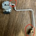
Unloader Line
The unloader line is typically a pipe that leads to the unloader valve. Unloader valves maintain the pressure process. One of their main functions is to restart and help the compressor operate sufficiently.
On a reciprocating compressor, like the single-stage compressor above, compressed air can be trapped over the piston when the compressor reaches the cut-out pressure and stops. If that air is unable to escape, a significant additional load is created for the start-up of the compressor motor when the pressure switch turns the compressor back on. That pressure build-up may be enough to prevent the compressor motor from starting due to overload.
When the compressor shuts off the typical unloader valve opens and unloads the air that may be trapped over the piston into the atmosphere, and that motor overload problem is resolved.
Pump to Tank Interconnect
In the pump to tank interconnect, compressed air is passed from the pump to the tank for storage through the in-tank check valve.
Pump
The air compressor pump is the core component responsible for generating compressed air. It is designed to suck in atmospheric air and compress it into smaller volumes creating greater pressures. The air is then stored in a storage tank and released through the discharge port through a hose so that the kinetic energy of the pressurized air can be used to power your pneumatic tools and devices.
While all parts of a compressor work together, the pump is arguably the most important component.
Air Cleaner
The air compressor air cleaner is a filter at the intake on the pump designed to block contaminants like dust and other debris in atmospheric air from entering the compression chamber in the pump.
If these were allowed to enter, they could potentially damage the internal mechanisms of the pump, causing premature wear and eventually complete failure.
Drain Port/Valve
To safeguard the air compressor system, water must be drained from the tank through the drain port and drain valve at the bottom. The amount of water in atmospheric air varies, and when this air is compressed, moisture or water naturally results from the air’s rise in temperature.
When compressed air is kept inside a tank, it naturally cools, causing moisture to condense and gather in the form of water droplets at the bottom of the tank. These droplets may erode the tank’s interior, resulting in corrosion on the interior walls. It is undesirable to have these rust particles and water in your airstream, especially if they prevent the air from reaching your air tools.
Therefore, it is recommended to drain your tank after every use to remove the water from the tank and protect your compressed air system and attached air tools.
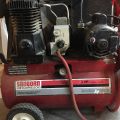
Two-Stage Air Compressor Diagram & Parts
Next up we have a two-stage stationary air compressor. Most of the parts of this compressor are similar to that of the single-stage, so I will only describe the ones that haven’t been described yet!
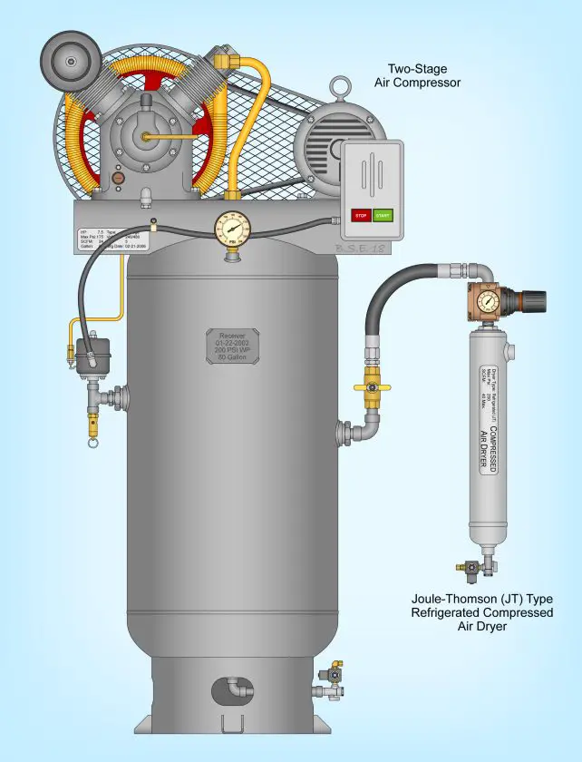
Bolt-Down Feet
Due to the fact that this is a stationary air compressor, they frequently include feet at the bottom of their vertical tank that you can screw into the ground to secure the compressor.
Safety Valve
All compression systems must use a safety valve, also referred to as a safety relief valve, as it is an essential safety element. These valves guard against the critical pressure equipment and pipework failing catastrophically.
A safety relief valve that is rated to open at a pressure no greater than the receiver’s maximum rating must be installed in every receiver.
In order to allow the valve to open at high pressure and remain open until the pressure has decreased to a noticeably lower pressure, typically around half of the valve’s pop-off pressure, the OD of the poppet in the valve tends to be significantly greater than the orifice size.
These are frequently mistaken for pressure relief valves, but they have different purposes.A pressure relief valve is intended to vent excess pressure from the system. These valves are, in a sense, a type of pressure regulator. When the pressure exceeds a preset level, the relief valve opens and bleeds down the system.
Pressure Switch
Devices called pressure switches enable or disable an electrical switch at a predefined setting. Both fixed pressure settings and adjustable settings are available for these switches.
The pressure switches in a compressed air system respond to a change in pressure by allowing or denying an outgoing signal that is used to start an operation. The action in the instance of our air compressor is to turn the air compressor’s electric motor on or off.
Welded Tank Tag/Machine Tag
All the necessary information about the system will be provided by the tags on the air compressor tank and the machine. Along with the storage capacity in gallons, the tank tag may also provide information about the shell and head thickness.
The compressor’s horsepower, SCFM rating, maximum permitted pressure, necessary voltages, kind of compressor, etc. will all be specified in the machine tag.
Intercooler
An intercooler is a mechanical heat exchanger that reduces the temperature of compressed air to close to the ambient to improve volumetric efficiency.
In a two-stage air compressor, an intercooler is frequently put in the line between the two cylinders to help cool the air before it is pulled into the next cylinder for additional compression in order to deal with the rising compressed air temperature.
Compressor Stages (First and Second)
Similar to a single-stage compressor, a two-stage air compressor also compresses air using a piston after being drawn into the cylinder. However, before being transferred to the storage tank for use with your attached pneumatic tools, the air is first pushed to a second, smaller piston for a second stroke at about 175 PSI.
Motor Controller
Since it includes all necessary control circuitry, the motor controller essentially serves as the motor starter. The motor controller will automatically turn off the device when energy conservation is required and will restart when pressure reaches a predetermined level.
You can schedule the times for loading and unloading using a controller. By doing this, you may minimize the amount of motor starts and short standstill times by keeping the unit operating when it’s necessary.
Isolation Valve
A shut-off valve, sometimes referred to as an air compressor isolation valve, is made to immediately stop the airflow if necessary. Usually, they have a lever that may be turned to immediately stop the air flow from the tank moving down the lines. Typically, these will be butterfly valves or gate valves.
Master Regulator
The master regulator is used to adjust the overall primary system pressure. You will set your tank regulator to a certain pressure and then utilize the master pressure regulator after the tank to control the pressure of the air through the lines and head to your pneumatic tools.
Most compressed air components are designed to operate at 90 psi. Therefore, supplying the distribution system with pressures higher than 90 psi is a waste. Using a master regulator on the output of the receiver will allow better utilization of the air charge, and consequently lower the cost per SCFM. This is especially true on two-stage air compressors like this example.
You should also be aware that a two-stage compressor can typically deliver 175 psi air, which is a high enough pressure to severely damage most air tools. Thus, showing the importance of a master regulator.
Refrigerated Air Dryer
Refrigerated compressed air dryers are one of the most commonly used types of air dryers due to their simple design, the fact they need very little maintenance, and their relative cheapness. The other types are desiccant and deliquescent air dryers.
In short, refrigerated compressed air dryers work by cooling down the air just like your refrigerator in your kitchen does to keep your produce fresh at the right temperature.
Rotary Screw Air Compressor & Dryer Diagram & Parts
Now, we switch our attention from reciprocating air compressors to a rotary screw air compressor.
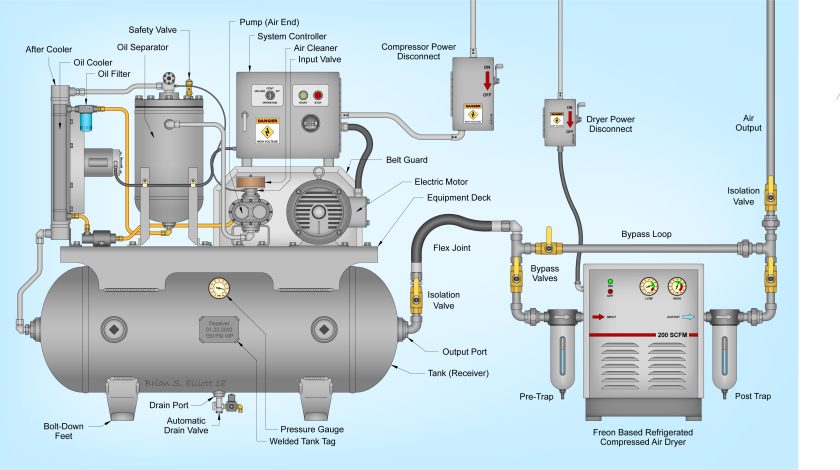
Automatic Drain Valve
This component is just like the tank drain valve previously described, and is there for the same purposes. The key difference is that the valve is designed to automatically release water from the tank and saves you from having to remember to manually drain the tank.
Aftercooler
Aftercoolers are mechanical heat exchangers designed to remove the heat of compression and reduce the amount of water vapor in compressed air systems by condensing the vapor into a liquid form.
An air compressor aftercooler has these three crucial primary functions:
- Cools air discharged from the air compressor
- Reduces the moisture level of the compressed air
- Protects downstream equipment from excessive moisture and heat
Oil Cooler
An oil cooler does exactly as its name implies, it cools down the oil within rotary screw air compressors that has become hot due to its role in lubricating the components involved in the compression stage. For the air compressor oil types visit my guide.
Oil Filter
Within any compressed air system, there exists a requirement for filtration. Oil is a particular problem in oil-lubricated systems, as the oil mixes in with the air during the compression stage, and so, must be removed from the air supply before it is allowed to enter the receiver tank. Typically, a Coalescent Filter is the best form of filter to tackle oil contamination.
Oil Separator
An oil separator is a filter within an air compressor system that separates oil from the compressed air to protect systems components and your air tools at the end of the line. An air-oil separator is similar to the oil filter just described.
However, the oil-water separator works by separating the oils and lubricants from liquid water. The oil-water separator collects condensate from the air compressor tank, filters and dryer then remove the oil from the water prior to draining it.
Compressor Power Disconnect
When an air compressor, or any device that uses a motor, as a matter of fact, starts up it draws up to 7 times it’s running AMPs. This is referred to as the air compressor startup amps. While it may only last for an instant it is a huge draw and any components that are not built to suit that kind of draw will, over time, fail. A standard switch will likely burn up under this amperage, and so, a correctly sized compressor power disconnect is necessary.
Flex Joint
The flex joint is there simply to connect the air compressor’s tank to the rest of the system. Flex joints are used in places to help reduce any vibration stress and protect against thermal growth. Due to the fact that the next stage of the compressed air systems piping is likely to be mounted securely against the wall, flex joints compensate for slight misalignments between the compressor and the airlines for an easy and reliable connection.
Bypass Valves
Hot gas bypass, or HGBP for short, is essentially a valve that automatically regulates the cooling temperature in the refrigerant air dryer exchanger based on the pressure of the refrigerant.
Refrigerant driers typically have a lower system pressure when they’re partially loaded. The hot gas bypass valve opens when the pressure in the refrigerant circuit decreases to allow some of the refrigerant to circumvent the heat exchanger, which helps to eliminate the problem of over-cooling. Hot gas bypass valve adjustment allows you to keep your dryer running at its optimal temperature without risking the health of your system.
FAQs (Frequently Asked Questions)
The basic parts of an air compressor include a motor, pump, storage tank, intake valve/filter, regulator, control panel, check valve, discharge line, outlet, and pressure switch to name a few!
You are likely to find the unloader valve mounted on or inside of the pressure switch on most air compressors. Therefore, when the pressure switch switches the air compressor off, the valve is actuated and unloads leftover air in the lines.
Air compressor breather elements allow air to be pumped within an air compressor system cleanly and efficiently. Breathers for air compressors keep the compressor and air tools that are being used to run smoothly and at their peak performance.
The two major components of an air compressor are its power source and compressing mechanism. The power source can be either an electric or fuel-powered motor while the compressing mechanism can be like a piston or rotary compression chamber for example.