
My thanks to Tony M. who was having a real problem with buying a new pressure switch. So far, he’s purchased two, and neither seems to work. So he’s looking for one that is similar to the one that came off his compressor. Let’s see if we can help him out.
What’s critical about a pressure switch?
Same pressure range!
You definitely want one that’s got the same pressure range capabilities of the old one. For example, if your old pressure switch cut in at 90 PSI to start pumping air again, sure you can use one that cuts in at 110 PSI, or 80 PSI.
If you acquire one that cuts in at 110 PSI, and the old one cut in at 90 PSI, odds are pretty good that your compressor is going to cycle on and off a whole lot more often, and that isn’t good for them.
If you get one that cuts out at 80 PSI, that’s less of an issue, yet it does mean that any air tool you have that needs 90 PSI to run will have its operation compromised a bit. Not a deal breaker, but probably not best. Buy a switch that has the same cut in, cut out, or one that is adjustable.
Same terminal locations?
Nah, that doesn’t matter, as long as the new switch is wired for 120 VAC, it will have two sides. One is the supply side (power cord) and the other is the load side (motor).
Each side will have one hot wire and one return (usually black for power and white for return).
The switch will also have a place on it for the “earth” or “ground” wire. That’s typically a smaller wire, and is often green. It is important to connect the ground wire to “earth” or “ground” terminal on the switch. It’s often a different color screw where the ground attached. Look for that, or the “earth” symbol.

Comparable voltage!
If a compressor needs 120 VAC to run, you don’t want a switch that controls 24 VDC as the switch would fail immediately!
The good news is that most switches on the market that control 120 VAC are also good for 240 VAC.
If your air compressor plugs into a wall socket, it’s running on 120 VAC in North America. Make sure the new switch has this voltage included in its operating range. In other countries, it is possible that a wall socket will provide 240 VAC, so do be sure.
How the pressure switch is mounted!
There a many styles and shapes of pressure switches on the market. You want to emulate the mounting of the old compressor pressure switch.
Since Tony was kind enough to send in the question with photos. Let’s focus on his switch mounting style for the moment.
Note that there is a threaded hole in the bottom of the mount. This thread is normally threaded onto a nipple that sticks up out of the tank. This nipple ensures that the diaphragm in the switch is exposed to the tank pressure, in order to react to the tank pressure to turn the compressor on, or turn the compressor off.
Some pressure switches are not mounted on a cast manifold, or may not be gray as the one shown above is, but all will have a threaded port to screw onto the nipple from the compressor tank.
The “manifold” shown in the photo above is simply a device to allow a variety of compressor components to be attached under the switch rather than elsewhere on the compressor.
For example, one of the ports in manifold will be there to allow a gauge to be threaded in. That gauge will show the tank pressure. That’s the one on the bottom in the photo and the back of the tank gauge can be seen.
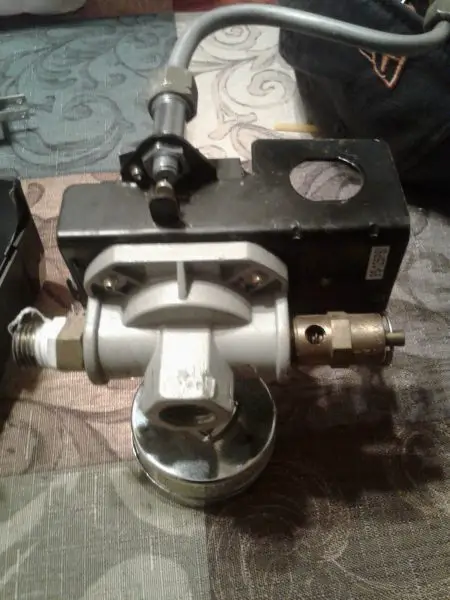
Here is another view of the compressor pressure switch manifold found on Tony’s compressor.

The nipple on the left of the photo above likely had the regulator threaded onto it, and then the other side of the regulator had the coupler into which the user inserted the connector from an air line.
Did you acquire a switch that didn’t have a manifold base like the one above. No worries. Make your own.
Visit a decent plumbing shop or hardware store, and buy enough tees, nipples and adapters and build your own.
The compressed air needs to get to the pressure switch, unimpeded. That’s important.
Weather the tank gauge is on one side or the other, as long as it gets air from the tank, it’s be fine.
The PRV too, has to have a direct feed from the tank. But it doesn’t have to be exactly the same location as the old switch.
There has to be a feed to the regulator too, so air can get out of the tank to be used.
Or, ensure that the switch you buy has a manifold base similar to the old pressure switch, and you are good to go.
Unloader valve?
What the unloader valve does is covered elsewhere on this site, so we won’t redo that page here.
Suffice to say that if the old switch had a unloader valve ( one shown on the side of the switch in the photo above) then the new switch MUST have an unloader valve too.
Some switches have an external unloader valve as shown in the photos above, and others have an internal unloader valve, where the line coming to the unloader as shown above is, instead, inserted into a fitting on the bottom of the pressure switch.
Whether or not the unloader valve is internal or external, the replacement switch must have an unloader.
If the old switch had an internal unloader and a switch with an external unloader was acquired, run the unloader line to the outside switch. It will work just fine. Or, if the reverse, the old switch had an external unloader (like those shown above) and the new switch has an internal unloader, simply plug the unloader line into the internal port, and all will be well.
On/Off switch?
Old pressure switch had an on/off switch, new one doesn’t? Who cares?
If you think about it, pulling the plug from the socket does the same thing as an on/off switch.
Sure, an on/off switch provides convenience, by allowing the operator to turn the compressor off at the switch. If you need an on/off switch and don’t have one, when work with the compressor is done, pull the plug from the socket! There’s your on/off switch.
Be aware!
You don’t need an on/off switch on a pressure switch. However, when the compressor cuts out when the tank is full, and if you leave the compressor plugged in when you are done work, if you have any leaks anywhere on the compressor or air line, the tank pressure will drop. When it drops far enough, the compressor will start.
That’s a waste of energy and, if the compressor is near where you are and it’s the middle of the night, nope, you don’t want that compressor starting up on its own.
So, if the old compressor switch had an on/off switch, and the new one doesn’t, make sure you remember to unplug it when you done working with compressed air.
Different base style of compressor pressure switch?
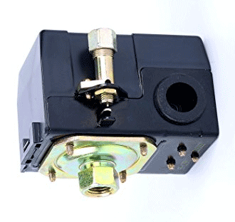
Unlike Tony’s, the switch in the photo above has no manifold base. Well, add a nipple in the bottom port, add a couple of tees, and you can create your own.
Questions or comments about buying a new replacement compressor pressures switch? Add them below.

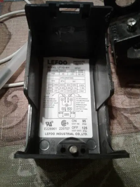
I have an older Bostitch wheelbarrow type air compressor that I need to replace the pressure switch on, but they no longer carry the original pressure switch so I had to buy a compatible one, and as it turns out it was made in China. The wiring connections inside are different then the old one and the new one does not have any markings inside for line and motor, nor does it have ground screws. I’m enclosing pics of the old one as well as the new one.
The new one is identical to the Lefoo LF10-L, with the exception no ground screws, where the ground screws are on the Lefoo there are 2 holes on my new one with the ground symbol underneath , which you can see in the pic.
My first question is can I just get 2 screws and screw them into the holes and use those for my grounds? a
Question #2 is does anyone happen to know which slots my line and motor wires go to in my new pressure switch? l
Like I said there are no markings anywhere on it and I can’t even find a wiring diagram for the Lefoo pressure switch, if I could at least find that somewhere, I’m pretty certain it would be the same layout as my new one.
The first pic is of the Lefoo pressure switch which is identical to the one I bought and you can see the ground, the next 2 pics are of my old pressure switch, and the remainder are of my new pressure switch and you can see the 2 screw holes that I think I can put 2 screws in and call that my ground.
Thank you anyone ahead of time that has any advice or opinions to try to help me figure out where the wires go on my new pressure switch.
P.S. I apologize but I just spent an hour trying to attach pics but it says it dont support the type of pics I’m trying to attach, so then I tried putting them in with the message but then it says my message is spam. If anyone has any ideas how I can post the pics please let me know.
If anyone thinks they can help me with the pressure switch wiring, please email me and I can send you the pics that way, I’m at a complete standstill because I don’t know how to wire the switch, and I cant figure out how to post pics on here for someone to help me. Thank you
Ron, you can upload one photo up to 5 MB or multiple photos up to a 5 MB total in size by clicking the “paper clip” icon bottom right in the comment. What format are the photos that you are trying to upload and my system says they cannot be uploaded? The system handles virtually any photo format. Please advise.
If there is a “ground or earth” screw hole in the switch, with no screws, I suspect it’s because getting screws and adding them adds cost, and everything from offshore is predicated on lowest price. In my opinion, and I am not an electrician (that’s who you should be asking) if the hole is market earth or ground, that’s where the ground wire goes.
Are you saying there are no markings for line / power side of the switch and no markings for load/motor on the switch at all? Weird.
Yes that’s correct, there are no marks anywhere on it indicating load/motor. As for the pics, I might have been trying to post too many at once, so Ill try just posting one or 2 at a time to see if that works. Thank you for making me aware of the size limit.
Update: I just tried to post a single pic, and I got this error message, “20200725_164109.jpg-Not allowed file type”. I’m not sure what I’m doing wrong but I took these photos with my Samsung Galaxy S9+ cell phone, the photos were saved to the gallery on my phone and I tried to posted them to this website from there. So Im not really sure what to do, I really wanted to share them on here in hopes someone could tell me where the line wires go and where the motor wires go
Ron, change the name of the photo to Ron1, Ron2 etc, or something like that. I think it may be the length of the image name that is the issue. Lots of folks have uploaded .jpg photos with no issue.
I tried that and it didn’t work, I know your probally getting tired of me bothering you with this so for the past couple days I’ve been trying everything I can think of to post the pics but each time I get the same error message, “jpg. not allowed file type” I even tried changing the name to just “1” and that didn’t work either. I then got my digital camera out and retook the pics, then downloaded them to my laptop and tried multiple ways to post them and every time I get that same error message, so I have absolutely no idea what the problem is or what I’m doing wrong. Many times I have taken photos and uploaded them different places and I’ve never had a problem. Do you have an email address I can send them to or a Facebook page I can post them too/ Or any other ideas for that matter, I’m very sorry for bothering you with all this. Will I damage anything if I just take a guess and wire the line wires to one side of the new switch and the motor wires to the other side? I was going to do that yesterday but thought I’d better ask someone in case I have them backwards. Thanks for your help
I am looking for this Pressure Switch….
Tony, hope this page helps.
http://fix-my-compressor.com/buying-a-new-replacement-pressure-switch/